While the great debate wages over the terms “expansion joints” vs. “control joints,” no one denies that they are both forms of “movement joints” and are necessary to prevent cracking in clay masonry veneer walls. Thus, it is important to understand the types of movement in clay-based masonry veneer walls and how to control the cumulative effects through the proper design of movement joints.
It has been said, “either you or nature will decide where to locate masonry movement joints, either way they will occur.” And while architects tend to like straight, clean lines for building movement, nature is not so particular. Unplanned movement in masonry walls often results in broken masonry units, unsightly cracks, and water intrusion into the building. Movement occurs both vertically and horizontally and occurs at different rates in dissimilar materials. Good design of movement joints requires the aesthetic placement of joints in locations necessary to accommodate anticipated movement.
DESIGNING WITH MASONRY MOVEMENT JOINTS
In order to accommodate for the total unrestrained movement of brick veneer, movement joints must be designed into the wall. The placement of these joints generally takes into consideration both the art and science of building design and functional aspects. The designer must consider building geometry (height, length, offsets in walls), materials, fenestrations, and building structural system. Brick veneer walls may include both horizontal and vertical joints, joints at dissimilar materials, and joints around wall penetrations.
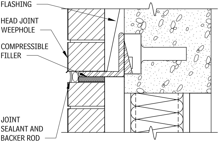
The building code prescribes a maximum supported height for anchored veneer masonry without an engineered design. This is typically about 30 ft. above the foundation or every two floors. Brick veneer is generally supported on steel shelf angles and provision for movement is provided immediately below the shelf angle. This includes a minimum ¼‐in. compressible material and a sealant joint. Some owners and designers object to large horizontal movement joints; lip brick may be used to minimize the apparent size of the joint.

RULES AND RECOMMENDATIONS FOR PLACING MOVEMENT JOINTS
Rules
- Align with building expansion joints
- Align with changes in backup assembly
- Sufficient number of joints to accommodate the total unrestrained movement of brick veneer
Recommendations
- Change in materials (differing thermal expansion coefficient)
- Near building corners (generally within 24 in.)
- Offsets in walls
- Every 20 to 24 ft. horizontally in straight wall runs
- No more than 15 ft. in parapet walls and locations where the masonry is subject to greater climate exposure
TYPES OF MOVEMENT JOINTS
Masonry Construction magazine offers a summary of the difference between “control joints” and “expansion joints”, which can be boiled down to this:
“A control joint is a continuous vertical joint filled with mortar, but with a bond breaker on one side so that tensile stress cannot develop across the joint … An expansion joint is a continuous vertical or horizontal joint, left completely free of mortar and filled with elastomeric sealant to keep it watertight.”
The difference, while subtle, is important to understand when planning out any brick veneer wall.
WHY MOVEMENT JOINTS ARE NEEDED
Building materials expand and contract based upon their design coefficient of thermal expansion. Differing materials are also subject to long‐term expansion or contraction due to moisture. Clay masonry absorbs moisture and expands while concrete masonry typically hydrates and shrinks. When dissimilar materials are used as part of the exterior cladding, and penetrations through walls of differing materials are subject to different rates of expansion, the wall design must accommodate this movement. Movement can occur at window openings, canopy attachments, precast concrete lintels, stone banding, and other similar areas.
CLAY MASONRY BASICS
Brick and tile are classified according to the specific location where they are used. Standard specifications have been developed to produce uniform requirements for brick. ASTM International publishes the most widely accepted standards on brick. Standard specifications include strength, durability, and aesthetic requirements.
CLAY MASONRY CLASSIFICATION TYPES
| TYPE OF BRICK UNIT | ASTM DESIGNATION |
| Building brick | C 62 |
| Facing brick | C 216 |
| Hollow brick | C 652 |
| Paving brick | C 902 |
| Paving brick (heavy vehicular) | C 1272 |
| Ceramic glazed brick | C 126 |
| Thin brick veneer units | C 1088 |
| Sewer and manhole brick | C 32 |
| Chemical‐resistant brick | C 279 |
| Industrial floor brick | C 410 |
| TYPE OF TILE UNIT | |
| Structural clay load‐bearing tile | C 34 |
| Structural clay non‐load‐bearing tile | C 56 |
| Structural clay facing tile | C 212 |
| Structural clay non‐load‐bearing screen tile | C 530 |
| Ceramic glazed tile | C 126 |
Terms used in each standard for brick classification may include exposure, appearance, physical properties, efflorescence, dimensional tolerances, distortion, chipping, core, and frogs. Brick may be classified by use, grade (exposure), and type (appearance). Properties should be identified. Each ASTM standard has minimum requirements for grade and type, which will be used as the default property if another is not specified.
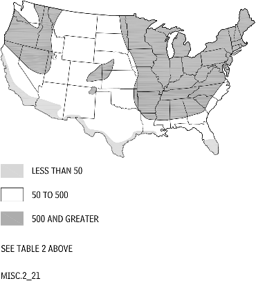
Specific grades of brick are required to accommodate the various climates in the United States and the different applications in which brick can be used. Brick grades include Severe Weathering (SW), Moderate Weathering (MW), and Negligible Weathering (NW); each is based on the weathering index and the exposure they will receive. The weathering index is the product of the average annual number of freezing cycle days and the average annual winter rainfall in inches (see Figure “U.S. WEATHERING INDEXES”). The exposure is related to whether the brick is used on a vertical or horizontal surface and whether the unit will be in contact with the earth (see Figure “EXPOSURE”). A higher weathering index or a more severe exposure will require face brick to meet the SW requirements. The grades for each specification are listed in Figure “GRADE REQUIREMENTS FOR FACE EXPOSURES”.

See this page for more.

